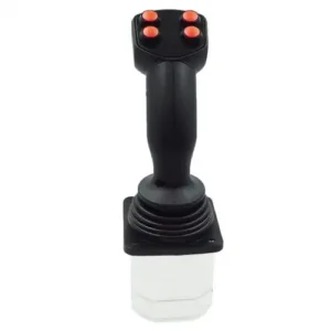


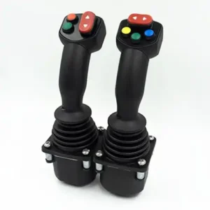
LT60 系列多功能眼鏡蛇搖桿
多重操作的 Cobra Control 控制搖桿可使用內建的按鈕開關、拇指輪和搖搖板運動電位器來操作複雜的功能。
應用範圍
本系列產品主要應用於起重機、裝載機、堆高機、挖掘機、拖拉機、收割機、垃圾車等。
技術資訊
電氣參數
電位器類型
| 電源電壓 | <36Vdc |
| 總電阻值 | 2kΩ、4kΩ、5kΩ、10kΩ |
| 電氣角度 | ± 18 ° |
| 中值電壓 | 48% ~ 52% (相對電源電壓) |
| 中值死角 | ± 2.5 ° |
| 電位器最大電壓 | 32Vdc |
| 電位器允許最大耗電量 | 0.25W |
大廳類型
| 電源電壓 | 5.0 ± 0.5Vdc |
| 電源電流 | <11mA (每個霍爾感測器) |
| 限制允許的過電壓 | 20Vdc |
| 反向極限容許電壓 | -10Vdc |
| 輸出電壓的線性誤差 | <± 0.2V |
方向開關
| 負載能力 | 2mA @ 30Vdc(電阻負載) |
| 起始角度 | ± 5 ° |
| 接觸電阻 | <200Ω |
配備轉換電路
| 電源電壓範圍 | 18 ~ 36Vdc (U 21 ~ U 24) |
| 9 ~ 36Vdc(電流輸出) | |
| 耗電電流 | <20mA |
| 最大輸出電流 | 10mA (標準電壓輸出時) |
CAN 匯流排類型
| 電源電壓 | 9 ~ 36Vdc |
| CAN 版本 CAN | 2.0B |
| 規範 | J1939 |
| 接頭 | 6 針插座 (Deutsch) |
微型開關
| 負載能力 | 4A @ 30Vdc(電阻負載) |
| 使用壽命 | 超過 3000 萬次 |
| 200,000 次或更多(電氣) | |
| 絕緣電阻 | > 100MΩ (500Vdc 絕緣電阻計) |
| 起始角度 | ± 3 ° ~ ± 5 ° |
機械參數
| 搖擺角度 | ± 20 ° |
| 操作模式 自動 | 彈簧回位 |
| 啟動力 | 5N |
| 最大操作力 | 11N |
| 限制力 | > 300N |
| 使用壽命 | > 2 百萬次 (電位器型) |
| > 5 百萬次(霍爾型) | |
| 重量 | 475 克(無上限) |
環境參數
| 工作溫度 -30 ℃ ~ + 70 ℃ |
| 儲存溫度 -40 ℃ ~ + 85 ℃ |
| 防護等級 IP65 (安裝面板上方) |
產品選擇
LT60 系列


操作方法
| 1A | 單軸前後方向 |
| 2AP | 2 軸橫向操作 |
| 2AC | 2 軸圓向操作 |
春季選擇
| L | 起始力 4.5N |
| M | 起始力 5N (預設值) |
| H | 起始力 9N |
輸出信號
電位器型 (電源電壓小於 36Vdc)
| P051 | 5KΩ 電位器 0% ~ 100% Vdc 電壓輸出 | |
| P052 | 5KΩ 電位器 10% ~ 90% Vdc 電壓輸出 | |
| P053 | 5KΩ 電位器 25% ~ 75% Vdc 電壓輸出 | |
| P101 | 10KΩ 電位器 0% ~ 100% Vdc 電壓輸出 |
普通霍爾型(供電電壓 5Vdc)
| H51 | 每軸單霍爾 0.5 ~ 2.5 ~ 4.5Vdc 電壓輸出 |
| H52 | 每軸單霍爾 0 ~ 2.5 ~ 5Vdc 電壓輸出 |
| H53 | 每軸單霍爾 1.25 ~ 2.5 ~ 3.75Vdc 電壓輸出 |
| H54 | 每軸單霍爾 1.0 ~ 2.5 ~ 4.0Vdc 電壓輸出 |
| H55 | 每軸單霍爾 1.15 ~ 2.5 ~ 3.85Vdc 電壓輸出 |
| 2H51 | 每軸雙霍爾 0.5 ~ 2.5 ~ 4.5Vdc 電壓輸出 |
| 2H52 | 每軸雙霍爾 0 ~ 2.5 ~ 5Vdc 電壓輸出 |
| 2H53 | 每軸雙霍爾 1.25 ~ 2.5 ~ 3.75Vdc 電壓輸出 |
| 2H54 | 每軸雙霍爾 1.0 ~ 2.5 ~ 4.0Vdc 電壓輸出 |
| 2H55 | 每軸雙霍爾 1.15 ~ 2.5 ~ 3.85Vdc 電壓輸出 |
備註:霍爾型也可使用 9 ~ 36V 的寬電壓,電壓輸出與上述相同;選擇前在普通霍爾型前加上 "W",如 W2H51,代表寬電壓,每軸有備援霍爾,0.5 ~ 2.5 ~ 4.5 Vdc 電壓輸出。
配備轉換電路
| U21 | power supply voltage 18 ~ 36Vdc, -10V ~ 0V ~ + 10V voltage output |
| U22 | power supply voltage 18 ~ 36Vdc,+ 10V ~ 0V ~ + 10V voltage output |
| U23 | power supply voltage 18 ~ 36Vdc, -5V ~ 0V ~ + 5V voltage output |
| U24 | power supply voltage 18 ~ 36Vdc,+ 5V ~ 0V ~ + 5V voltage output |
| I21 | power supply voltage 9 ~ 36Vdc, two-wire system 4mA ~ 12mA ~ 20mA current output |
| I22 | power supply voltage 9 ~ 36Vdc,two-wire system 20mA ~ 4mA ~ 20mA current output |
CAN bus type (power supply voltage 9 ~ 36Vdc)
| J33 | CAN 2.0B bus output,source address is 33 |
| J34 | CAN 2.0B bus output,source address is 34 |
| J35 | CAN 2.0B bus output,source address is 35 |
| J36 | CAN 2.0B bus output, source address is 36 |
Attention please:If you want to choose 2 can bus joystick used on a same equipment,please choose 2 different source address.
Other
NA (no analog signal output)
Micro switch (not available when CAN bus is output)
| MS00 | without micro switch |
| MS12 | with 4A front and back position micro switch not available for dual-axis cross direction operation |
把手上端
| HA | HA handle no button on top |
| HAS | HAS handle with button on top |
| HD | HD handle no button on top |
| HDS | HDS handle with button on top |
| HDR | HDR handle with rocker on top |
| KGDN | KG handle with deadman switch, no rocker |
| KGDR | KG handle with deadman switch and seesaw |
| SS | For details please refer to the description of the grip of the SS/SA/SP handle |
Outgoing way
| D | Dechi connector (only CAN bus output) |
| A | AMP 連接器 |
尺寸

產品安裝


電氣裝置
Deutsch (Deutsch) socket
Pin number CAN output color
| 1 Ground (GND) black |
| 2 Power supply (VCC) red |
| 3 CAN high yellow |
| 4 CAN low green |
| 5 CAN shield N / A |
| 6 Empty (N / A) N / A |
AMP 連接器
16 core interface
Pin No. P Potentiometer Series H Hall Series U Conversion Circuit Voltage Conversion Circuit Voltage
| 1 Y-axis front direction switch Button switch 4 Button switch common terminal Button switch common terminal |
| 2 Empty (N / A) button switch 3 Button switch 1 Button switch 1 |
| 3 X axis potentiometer left end button switch 2 button switch 2 button switch 2 |
| 4 Slide end of X-axis potentiometer Button switch 1 Button switch 3 Button switch 3 |
| 5 Right end of X-axis potentiometer Top button Push button switch 3 Push button switch 3 |
| 6 X axis potentiometer center end button switch 5 button switch 5 button switch 5 |
| 7 X axis switch common end button switch 6 button switch 6 button switch 6 |
| 8 X-axis left direction switch Safety switch Top button Top button |
| 9 Y-axis potentiometer rear button switch 9 safety switch safety switch |
| 10 Y-axis potentiometer sliding end button switch 10 safety switch safety switch |
| 11 Front end of Y-axis potentiometer Button switch common terminal X-axis left direction switch X-axis left direction switch |
| 12 Y-axis potentiometer center end safety switch X-axis right direction switch X-axis right direction switch |
| 13 Y axis switch common end empty Y axis back direction switch X axis switch common end |
| 14 Y-axis rear direction switch empty Y-axis front direction switch Y-axis rear direction switch |
| 15 X axis right direction switch empty switch common Y axis front direction switch |
| 16 empty (N / A) Y-axis switch common |
12 core interface
Foot number P potentiometer series H Hall series (5V)
| 1 Button switch 4 + 5V power supply (redundant) |
| 2 Button switch 3 0V power supply (redundant) |
| 3 Button switch 2 + 5V power supply |
| 4 Button switch 0V power supply |
| 5 Top button Y axis output (redundant) |
| 6 Button switch 5 X axis output |
| 7 Button switch 6 X-axis output (redundant) |
| 8 Safety switch Y axis output |
| 9 Button switch 9 Z1 axis output |
| 10 Button switch 10 Z2 axis output |
| 11 Button switch common Z1 axis output (redundant) |
| 12 Safety switch Z2 axis output (redundant) |
※ Standard Hall output, use 3/4/6/8 pin outlet
8-core interface
Footnote H Hall Series Conversion Circuit
| 1 Front direction micro switch common terminal VCC |
| 2 Front direction micro switch output GND |
| 3 Output terminal of micro switch in the rear direction X-axis output |
| 4 Y axis output of the common terminal of the back direction micro switch |
| 5 Left side micro switch public end Out com |
| 6 Output terminal of micro switch in the left direction NA |
| 7 Micro switch output terminal in the right direction NA |
| 8 Common terminal of the micro switch in the right direction NA |

