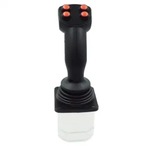


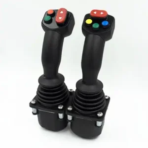
LT60 시리즈 다기능 코브라 조이스틱
Multi-operational Cobra Control joystick can be used to operate complex functions with incorporated push button switches,thumb wheel and seesaw motion potentiometer.
적용 범위
This series of products are mainly used in cranes, loaders, forklifts, excavators, tractors, harvesters, Garbage truck etc.
기술 정보
전기 매개변수
Potentiometer type
| Power supply voltage | <36Vdc |
| 총 저항 값 | 2KΩ, 4KΩ, 5KΩ, 10KΩ |
| 전기 각도 | ± 18 ° |
| 중앙값 전압 | 48% ~ 52%(상대 전원 공급 전압) |
| 데드존 각도 중앙값 | ± 2.5 ° |
| 전위차계 최대 전압 | 32Vdc |
| 전위차계로 최대 전력 소비 허용 | 0.25W |
Hall type
| Power supply voltage | 5.0 ± 0.5Vdc |
| 전원 공급 장치 전류 | <11mA (each Hall sensor) |
| 허용 과전압 제한 | 20Vdc |
| 역방향 제한 허용 전압 | -10Vdc |
| 출력 전압의 선형 오차 | <± 0.2V |
Direction switch
| Load capacity | 2mA @ 30Vdc(저항 부하) |
| 시작 각도 | ± 5 ° |
| 접촉 저항 | <200Ω |
With conversion circuit
| Power supply voltage range | 18 ~ 36Vdc (U 21 ~ U 24) |
| 9 ~ 36Vdc (current output) | |
| Power consumption current | <20mA |
| Maximum output current | 10mA (at standard voltage output) |
CAN bus type
| Power supply voltage | 9 ~ 36Vdc |
| CAN version CAN | 2.0B |
| Protocol | J1939 |
| connector | 6-pin socket (Deutsch) |
Micro Switch
| Load capacity | 4A @ 30Vdc (resistive load) |
| 서비스 수명 | more than 30 million times (mechanical) |
| 200,000 times or more (electrical) | |
| Insulation resistance | > 100MΩ (500Vdc insulation resistance meter) |
| 시작 각도 | ± 3 ° ~ ± 5 ° |
기계적 매개 변수
| 흔들림 각도 | ± 20 ° |
| Mode of operation Automatic | spring return |
| 시작 힘 | 5N |
| 최대 작동력 | 11N |
| 힘 제한 | > 300N |
| 서비스 수명 | > 2 million times (potentiometer type) |
| > 5 million times (Hall type) | |
| 무게 | 475g (no upper end) |
환경 매개 변수
| Working temperature -30 ℃ ~ + 70 ℃ |
| Storage temperature -40 ℃ ~ + 85 ℃ |
| Protection grade IP65 (above the installation panel) |
제품 선택
LT60series


작동 방법
| 1A | single axis front-back direction |
| 2AP | 2-axis operate in cross direction |
| 2AC | 2-axis operate in round direction |
Spring selection
| L | starting force 4.5N |
| M | Starting force 5N (default) |
| H | starting force 9N |
출력 신호
Potentiometer type (power supply voltage is less than 36Vdc)
| P051 | 5KΩ potentiometer 0% ~ 100% Vdc voltage output | |
| P052 | 5KΩ potentiometer 10% ~ 90% Vdc voltage output | |
| P053 | 5KΩ potentiometer 25% ~ 75% Vdc voltage output | |
| P101 | 10KΩ potentiometer 0% ~ 100% Vdc voltage output |
Ordinary Hall type (supply voltage 5Vdc)
| H51 | Single Hall per axis 0.5 ~ 2.5 ~ 4.5Vdc voltage output |
| H52 | single Hall per axis 0 ~ 2.5 ~ 5Vdc voltage output |
| H53 | Single Hall per axis 1.25 ~ 2.5 ~ 3.75Vdc voltage output |
| H54 | Single Hall per axis 1.0 ~ 2.5 ~ 4.0Vdc voltage output |
| H55 | Single Hall per axis 1.15 ~ 2.5 ~ 3.85Vdc voltage output |
| 2H51 | Double Hall for each axis 0.5 ~ 2.5 ~ 4.5Vdc voltage output |
| 2H52 | Double Hall for each axis 0 ~ 2.5 ~ 5Vdc voltage output |
| 2H53 | Double Hall for each axis 1.25 ~ 2.5 ~ 3.75Vdc voltage output |
| 2H54 | Double Hall for each axis 1.0 ~ 2.5 ~ 4.0Vdc voltage output |
| 2H55 | Double Hall for each axis 1.15 ~ 2.5 ~ 3.85Vdc voltage output |
Remarks: The Hall type can also be used with a wide voltage of 9 ~ 36V, the voltage output is the same as above; the selection is preceded by an ordinary Hall type with “W”, such as W2H51, representing a wide voltage, redundant Hall for each axis, 0.5 ~ 2.5 ~ 4.5 Vdc voltage output.
With conversion circuit
| U21 | power supply voltage 18 ~ 36Vdc, -10V ~ 0V ~ + 10V voltage output |
| U22 | power supply voltage 18 ~ 36Vdc,+ 10V ~ 0V ~ + 10V voltage output |
| U23 | power supply voltage 18 ~ 36Vdc, -5V ~ 0V ~ + 5V voltage output |
| U24 | power supply voltage 18 ~ 36Vdc,+ 5V ~ 0V ~ + 5V voltage output |
| I21 | power supply voltage 9 ~ 36Vdc, two-wire system 4mA ~ 12mA ~ 20mA current output |
| I22 | power supply voltage 9 ~ 36Vdc,two-wire system 20mA ~ 4mA ~ 20mA current output |
CAN bus type (power supply voltage 9 ~ 36Vdc)
| J33 | CAN 2.0B bus output,source address is 33 |
| J34 | CAN 2.0B bus output,source address is 34 |
| J35 | CAN 2.0B bus output,source address is 35 |
| J36 | CAN 2.0B bus output, source address is 36 |
Attention please:If you want to choose 2 can bus joystick used on a same equipment,please choose 2 different source address.
Other
NA (no analog signal output)
Micro switch (not available when CAN bus is output)
| MS00 | without micro switch |
| MS12 | with 4A front and back position micro switch not available for dual-axis cross direction operation |
손잡이 상단
| HA | HA handle no button on top |
| HAS | HAS handle with button on top |
| HD | HD handle no button on top |
| HDS | HDS handle with button on top |
| HDR | HDR handle with rocker on top |
| KGDN | KG handle with deadman switch, no rocker |
| KGDR | KG handle with deadman switch and seesaw |
| SS | For details please refer to the description of the grip of the SS/SA/SP handle |
Outgoing way
| D | Dechi connector (only CAN bus output) |
| A | AMP connector |
치수

Product Installation


Electrical Installations
Deutsch (Deutsch) socket
Pin number CAN output color
| 1 Ground (GND) black |
| 2 Power supply (VCC) red |
| 3 CAN high yellow |
| 4 CAN low green |
| 5 CAN shield N / A |
| 6 Empty (N / A) N / A |
AMP connector
16 core interface
Pin No. P Potentiometer Series H Hall Series U Conversion Circuit Voltage Conversion Circuit Voltage
| 1 Y-axis front direction switch Button switch 4 Button switch common terminal Button switch common terminal |
| 2 Empty (N / A) button switch 3 Button switch 1 Button switch 1 |
| 3 X axis potentiometer left end button switch 2 button switch 2 button switch 2 |
| 4 Slide end of X-axis potentiometer Button switch 1 Button switch 3 Button switch 3 |
| 5 Right end of X-axis potentiometer Top button Push button switch 3 Push button switch 3 |
| 6 X axis potentiometer center end button switch 5 button switch 5 button switch 5 |
| 7 X axis switch common end button switch 6 button switch 6 button switch 6 |
| 8 X-axis left direction switch Safety switch Top button Top button |
| 9 Y-axis potentiometer rear button switch 9 safety switch safety switch |
| 10 Y-axis potentiometer sliding end button switch 10 safety switch safety switch |
| 11 Front end of Y-axis potentiometer Button switch common terminal X-axis left direction switch X-axis left direction switch |
| 12 Y-axis potentiometer center end safety switch X-axis right direction switch X-axis right direction switch |
| 13 Y axis switch common end empty Y axis back direction switch X axis switch common end |
| 14 Y-axis rear direction switch empty Y-axis front direction switch Y-axis rear direction switch |
| 15 X axis right direction switch empty switch common Y axis front direction switch |
| 16 empty (N / A) Y-axis switch common |
12 core interface
Foot number P potentiometer series H Hall series (5V)
| 1 Button switch 4 + 5V power supply (redundant) |
| 2 Button switch 3 0V power supply (redundant) |
| 3 Button switch 2 + 5V power supply |
| 4 Button switch 0V power supply |
| 5 Top button Y axis output (redundant) |
| 6 Button switch 5 X axis output |
| 7 Button switch 6 X-axis output (redundant) |
| 8 Safety switch Y axis output |
| 9 Button switch 9 Z1 axis output |
| 10 Button switch 10 Z2 axis output |
| 11 Button switch common Z1 axis output (redundant) |
| 12 Safety switch Z2 axis output (redundant) |
※ Standard Hall output, use 3/4/6/8 pin outlet
8-core interface
Footnote H Hall Series Conversion Circuit
| 1 Front direction micro switch common terminal VCC |
| 2 Front direction micro switch output GND |
| 3 Output terminal of micro switch in the rear direction X-axis output |
| 4 Y axis output of the common terminal of the back direction micro switch |
| 5 Left side micro switch public end Out com |
| 6 Output terminal of micro switch in the left direction NA |
| 7 Micro switch output terminal in the right direction NA |
| 8 Common terminal of the micro switch in the right direction NA |

